9. Relative motion
9.1. Overview
Links to programs in this lesson:
You probably have a good sense of what relative motion is already. For example, if you are driving down the road in a car, everything going on inside the car will usually appear to be at rest. This is because everything in the car has the same velocity that you do, so your “relative” velocities are zero. On the other hand, you will see the cars going in the opposite direction at a really high speed. It is not that they are actually moving this fast (at least according to a bystander on the ground!), but the cars’ velocities combine together to produce the high velocity you see. Relative motion deals with how moving objects appear to each other. Vectors will be important here, since the direction of the objects’ velocities can change the resulting relative motion. In fact, such ideas are used in ship navigation, where a maneuvering board (or “moboard”) provides a convenient way of doing relative motion vector calculations. Although they are slower than electronic means, it is always a good idea to know what your equipment is doing, so you can evaluate it properly.
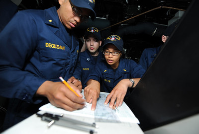
Fig. 9.1 Sailors plot ship positions on a maneuvering board on the bridge of the guided-missile destroyer USS Truxtun (DDG 103) during a divisional tactics exercise. Truxtun is deployed as part of the George H.W. Bush Carrier Strike Group supporting maritime security operations and theater security cooperation efforts in the U.S. 5th and 6th Fleet areas of responsibility. (U.S. Navy photo by Mass Communication Specialist 3rd Class Kevin J. Steinberg/Released) (source)
Here are the objectives for this lesson:
State the relative motion equation relating velocities.
Calculate the velocity of one object, moving relative to a stationary observer, as seen by another object moving relative to the stationary observer.
9.2. Relative motion
Relative motion is when two or more objects are moving in relation to each other, and need to calculate the velocity of one object as seen by the other. The important part of doing this correctly is to be particular about who is seeing what! This is done by ensuring we define our quantities, and being careful to use these definitions.
First, we define
The order is important! If I am moving northward as seen by you, then you are seen by me as moving with the same speed but southward. This means that
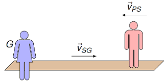
Fig. 9.2 Watching someone on a moving sidewalk
Suppose you are on the ground watching another person walking on a moving sidewalk, with the person (P) on the moving sidewalk (S), and you on the ground (G). The velocity \({\vec v}_{PG}\) of the person as seen by you is the sum of the person’s velocity on the sidewalk added (as a vector!) to the velocity of the sidewalk as seen by the ground, or
A word of caution
These two equations are all you need to do any relative motion problem. It is important to make sure you understand that all of your intuition about relative motion are in these equations, as long as you remember to use vectors and not magnitudes. One thing I have noticed students do is they try to second-guess these equations – for example, by changing the signs in the second equation to match which way an object is moving according to an observer. Don’t do this! The hard part of relative motion is finding the vectors for each of the object velocities; once you have done this, the relative motion equations do all of the work for me – don’t overthink them!
Problem
You are walking at 2.00 m/s due west on the moving sidewalk, which is moving at 2.50 m/s due east. What does a stationary security guard see as your velocity? Select the best choice below.
4.50 m/s due west
2.00 m/s due west
50.0 cm/s due east
2.00 m/s due east
4.50 m/s due east
Answer: Let “\(Y\)” represent your reference, “\(G\)” for the guard/ground, and “\(S\)” for the moving sidewalk. Then, if
giving
Thus, the guard sees you moving at 50.0 cm/s due east.
Problem
Building off the last question, you stand in place on the moving sidewalk, which is still moving at 2.50 m/s due east. If the guard is walking 2.00 m/s due east, what does the guard see as your velocity? Choose the best answer.
4.5 m/s due west
2.0 m/s due west
0.5 m/s due east
2.0 m/s due east
4.5 m/s due east
Answer: Let “\(Y\)” represent your reference (the same as the sidewalk), “\(G\)” for the guard, and “\(F\)” for the floor. Our equation is now
where we had to write it in terms of the guard’s velocity according to the floor in the last step. This gives
Thus, the guard sees you moving at 50.0 cm/s due east; the answer is the same as above, but due to a different set of motions.
Problem
Suppose you are standing on the ground (G) along a train track while a train (T) moves to the right at 15.0 m/s. On the train is a person (P) who is moving left on the train at 1.20 m/s.
What is the velocity (magnitude in m/s) of the person as seen by you? In other words, what is \({\vec v}_{PG}\)?
Suppose the person switches directions, and walks to the right, but at the same speed. What is \({\vec v}_{PG}\) now (magnitude in m/s)?
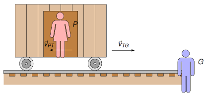
Fig. 9.3 Watch a hobo pass by on a moving train
Answers: 13.8 m/s, to the right; 16.2 m/s, to the right
Problem
Three cars, A, B, and C, are moving along a straight section of a highway, taken as the \(x\) axis. The velocity of A as seen by B is \({\vec v_{AB}}\), the velocity of A seen by C is \({\vec v_{AC}}\), and the velocity of C seen by B is \({\vec v_{CB}}\). Fill in the missing \(x\) velocity components in the table below.
\(v_{AB, x}\) (m/s) |
\(v_{AC, x}\) (m/s) |
\(v_{CB, x}\) (m/s) |
|---|---|---|
\(+40.0\) |
\(+30.0\) |
|
\(+50.0\) |
\(-20.0\) |
|
\(+60.0\) |
\(-20.0\) |
|
\(-50.0\) |
\(+10.0\) |
Answer: You need to complete the table using the vector equation
Specifically, you just use the \(x\) components of this equation. This gives the results shown below.
\(v_{AB, x}\) (m/s) |
\(v_{AC, x}\) (m/s) |
\(v_{CB, x}\) (m/s) |
|---|---|---|
\(+70.0\) |
\(+40.0\) |
\(+30.0\) |
\(+30.0\) |
\(+50.0\) |
\(-20.0\) |
\(+60.0\) |
\(-20.0\) |
\(+80.0\) |
\(-50.0\) |
\(-60.0\) |
\(+10.0\) |
9.3. 1D relative motion in vPython
9.3.1. Creating the scene
To help you get a better feeling of relative motion, we will go through some examples in vPython. There will be different perspectives on the same motion; changing which viewpoint you see the motion from will change how it appears. The first case you will look at is two objects moving along the \(x\) axis. There will be objects R (red sphere) and B (blue sphere), both in motion on top of a green box, the ground (G).
Most of the code in the program below should be familiar to you, but it is worthwhile to go through the parts before we get to what is different than previous cases. It is probably helpful before you run the program below to look through the code as you read through the description given next.
As always, the code starts with defining time related variables MAX_TIME, t and DT. After that, there are three objects created: two spheres, a red sphere objR (object R) and a blue sphere objB (object B). Both of these spheres are on top of a third object, a green box ground (object G). The only extra piece here is that the objects R and B create a trail, which means there is a line indicating the path of each object. You will see that these trails look different, depending on which object’s perspective we are using. At the start, it will be how all objects move as seen by the ground. At the end of the code, there is the usual while to update the positions of R, B and G.
What is new about the code are the velocities. It is important to realize that there are two velocities that are important for each object. The first velocities defined are the velocities velRG, velBG and velGG. These are the velocities of the objects as seen by the ground G – in other words, the vectors \({\vec v}_{RG}, {\vec v}_{BG}\) and \({\vec v}_{GG}\). Since the ground is not moving relative to itself, obviously \({\vec v}_{GG} = {\vec 0}\)!
The second set of velocities objR.velocity, objB.velocity and ground.velocity tell the computer what motion to show when the program is run. This is not necessarily the same as the velocities of the objects as seen by the ground, since we can take the perspective of a different object, as we will do later.
Run the program now, and see how objects R and B move relative to the ground.
The velocity velRG was chosen so that the red sphere R moves to the right, while velBG was chosen so that the blue sphere B moves at a faster rate to the left. The two objects start at opposite sides of the ground, and pass each other about halfway along.
9.3.2. The viewpoint of the red sphere
Next we change the viewpoint, so it is how things are seen by object R. To do this, we will keep the three velocities velRG, velBG and velGG the same, and use them to change the velocities objR.velocity, objB.velocity and ground.velocity the computer uses to show the motion. Since we are using the perspective of object R, we need these velocities to be \({\vec v}_{RR}\) (the velocity of R as seen by itself) and \({\vec v}_{BR}, {\vec v}_{GR}\) (the velocities of B and the ground as seen by R).
To think about how to change the code in the orogram above, we go back to the relative motion equation, and look at the velocity of the blue sphere B. The velocity \({\vec v}_{BR}\) is defined as
Since \({\vec v}_{GR}\) (the velocity of the ground as seen by object R) is equal to \(-{\vec v}_{RG}\) (the velocity of R as seen by the ground), then
If it is helpful, you can also start with the motion of B as seen by ground,
and subtract the vector \({\vec v}_{RG}\) from both sides to get the same equation.
So, with this in mind, to animate the velocity of object B as seen by object R properly, you need to change the definition of objB.velocity in the program above so it now says
objB.velocity = velBG - velRG
Because object R is moving with respect to the ground, the ground appears to be moving according to object R. Thus, you need to change ground.velocity, too. You could use the fact that \({\vec v}_{GR} = - {\vec v}_{RG}\), but we will use something more sophisticated to get the same result. Starting from
similar to what we did above, \({\vec v}_{GR} = - {\vec v}_{RG}\), so that the end result is
Note that \({\vec v}_{GG} = {\vec 0}\), so this is a long-winded way of saying \({\vec v}_{GR} = - {\vec v}_{RG}\)! The reason for this method will be explained in a moment, but first, you need to change the line defining ground.velocity to
ground.velocity = velGG - velRG
Why are we doing it this odd way? Hopefully you are picking up on the pattern – for both object B and the ground, you are starting with their velocities as seen by the ground, and subtracting \({\vec v}_{RG}\) from both to get their velocities as seen by object R.
In fact, we can keep going in order to change objR.velocity. Since we want to show the velocity of R as seen by R, then by the same logic as above,
In the original program above, change objR.velocity so that it reads
objR.velocity = velRG - velRG
Since \({\vec v}_{RG} - {\vec v}_{RG} = {\vec 0}\), then \({\vec v}_{RR} = {\vec 0}\) – the red sphere is not moving according to itself (as expected!). After you have changed the definitions of the three velocities objR.velocity, objB.velocity and ground.velocity, run the program and see how the animation has changed.
Does the motion of all three objects make sense from the perspective of object R? You should see the following:
The red sphere R does not appear to move, and leaves no trail. You are viewing the system from the perspective of object R.
The ground G is now moving to the left. Remember this is the same as saying that the red sphere R is moving to the right according to the ground.
The blue sphere B is moving to the left still, but is now moving faster, and leaves a long trail. Object B is moving faster according to the red sphere R than it is according to the ground G, since R and B are moving in opposite directions.
9.3.3. The viewpoint of the blue sphere
Next, you will change the program above so that it shows the viewpoint of the blue sphere, object B. Again, the only changes you will need to make are in defining objR.velocity, objB.velocity and ground.velocity. Just like before, you will subtract the same vector from objR.velocity, objB.velocity, and ground.velocity to get the new velocities as seen by object B. See if you can figure out what this vector is, make the needed changes, and then run the program again.
If you have edited the code correctly, you should see the following in the new animation:
The blue sphere B does not appear to move, and leaves no trail. You are viewing the system from the perspective of object B.
The ground G is now moving to the right. Remember this is the same as saying that the blue sphere B is moving to the left according to the ground. The ground should also have moved further to the right than it did when viewed from R’s perspective! This is because the velocity of object B according to the ground is faster than A’s velocity seen by the ground.
The red sphere R is still moving to the right, but faster according to B than it was according to the ground.
The displacement the red sphere R travels according to the blue sphere B is the same size but opposite direction to the displacement of the blue sphere B as seen by R. You can see this by the fact that R’s trail here is the same length as B’s trail was when seen by the red sphere. Again, \({\vec v}_{RG} = - {\vec v}_{GR}\), so they see each other with the same speed, but moving in opposite directions!
The final step for one-dimensional motion will be to change the starting positions and velocities of objects R and B, and then see what the motion looks like according to (1) the ground, (2) object R, and (3) object B. Change the starting positions of the red and blue spheres so that objR.pos = vector(-5, -1, 0) and objB.pos = vector(-5, 1, 0). Then change velBG so that velBG = vector(2, 0, 0).
Modify the code so that it is seen from the viewpoint of the ground and then run the program. You will see the red and blue spheres start at the left side of the ground and move to the right, with the blue sphere moving faster. Then change the code so that the animation is seen from first R’s perspective, and then from B’s perspective. Are the results what you expect?
9.4. 2D relative motion
9.4.1. Crossing a river
The next scenario you will work on is the case of an object crossing a moving river. It will be your goal to get the object to cross directly across the river. This will involve doing some calculations with two-dimensional relative motion.
Suppose you are driving an assault amphibious vehicle (AAV), which can travel both on ground and across water. There are three frames of reference here: the vehicle V, the water W of the river, and the ground G. The river’s current is \({\vec v}_{WG}\), the velocity of the water as seen by the ground. When the AAV is traveling on the water, the motor of the AAV causes it to move with a set velocity with respect to the surface of the water. This velocity is \({\vec v}_{VW}\). The current of the water the AAV is moving on will change the velocity of the vehicle as seen by someone standing on the ground, or \({\vec v}_{VG}\). So \({\vec v}_{VW}\), the vehicle’s water speed, is constant, but the vehicle’s speed according to the ground, \({\vec v}_{VG}\), will vary depending on the current.
As the 1D case, it is probably helpful to read through the explanation of the code given next before you run the program below, since there are a few added parts. The first is that three objects – shoreNorth, shoreSouth and river – are created, and then combined using the compound module into a single object ground. From this point on, this will be the reference frame ground (G) used in the code, i.e. not the individual objects. After this, a vehicle object is created.
The next new part is dealing with the velocity of the AAV. First, a velocity vector velV is defined. This is the velocity of the vehicle on whatever surface it is on at the moment. If the AAV is driving on the ground, then its velocity \({\vec v}_{VG}\) is given by velV. On the other hand, if the AAV is on water, then velV is now the velocity \({\vec v}_{VW}\) of the AAV on the water, not the ground.
Finally, the ground is shown as stationary in the animation, so the velocity \({\vec v}_{VG}\) of the vehicle as seen by the ground must be determined for all cases. The code needs to check whether the AAV is on the water or on the ground in order to give it the correct velocity. If the AAV is on the ground, then it simply moves with its velocity \({\vec v}_{VG}\) (which is velV) from the ground’s viewpoint. However, when the vehicle is on the water, we know both \({\vec v}_{VW}\) and \({\vec v}_{WG}\), and so the velocity of the AAV in the ground’s viewpoint is given by
Inside the while loop, there is an if statement to figure out which of the two velocities to use. Since the AAV is moving in the \(+y\) direction, the test is whether vehicle.pos is within the \(y\) boundaries of the river, which are \(y = +2\) and \(y = -2\).
Now run the program below, and make sure the motion matches what you would expect. The movement of the AAV on the ground and the water is determined by velV and velWG.
When you run the program above, you will see the white box representing the AAV move towards the top of the window when it is moving on the green ground. However, when the vehicle is on the blue water, it is carried downstream to the left at the same time it is moving upwards – its motion on the water is a combination of the two. The AAV lands on the upper bank downstream from where it entered the water. The relationship between the three velocity vectors is shown in the figure below.
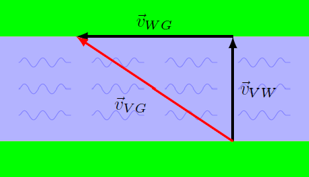
Fig. 9.4 Relative motion vectors for the AAV carried downstream
From the definitions of velV and velWG, you can see that the speed of the vehicle on the water \(v_{VW} = 2\), while the speed of the current \(v_{WG} = 1.5\). From this and the triangle above, you can calculate the speed \(v_{VG}\) of the AAV as it is seen from the ground.
Problem
Calculate this speed \(v_{VG}\). Remember that there is a \(90^\circ\) angle between the vectors \({\vec v}_{WG}\) and \({\vec v}_{VW}\).
Answer: Since the two vectors are perpendicular, you can use the Pythagorean theorem to find the magnitude of the AAV’s velocity while on the water. This gives 2.50 m/s.
If we want the AAV to land on the opposite shore directly across from where it went into the water, then the appropriate diagram should be more like the one below. Take some time to see how the triangle given is different than the previous one. Note that the speed of the current \(v_{WG}\) is still the same as above, but the direction the AAV is moving relative to the water must change. This ensures the vehicle lands directly across the river, as seen by the ground. The AAV needs to point upstream, so that the net result is a velocity \({\vec v}_{VG}\) is exactly in the \(+y\) direction.
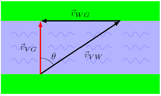
Fig. 9.5 Relative motion vectors for the AAV aiming upstream
Problem
Using the same values as before for \(v_{VW}\) and \(v_{WG}\), calculate the angle the AAV would have to point upstream (\(\theta\) in the diagram above) so that it moves directly across the river. Now the \(90^\circ\) angle is between \({\vec v}_{WG}\) and \({\vec v}_{VG}\).
Answer: Now the hypotenuse is 2.00 m/s, not one of the sides. Using the inverse sine function, you get \(\theta = 48.6^\circ\).
Problem
Calculate the new speed \(v_{VG}\) as it moves across the water in this case. Is it faster or slower than before?
Answer: Using the Pythagorean theorem (or one of the inverse trignometric functions), the speed \(v_{VG}\) is 1.32 m/s. The AAV is moving slower, since some of its velocity is “canceled” by the river current.
To check your answer, change the velocity velV in the program above so that the AAV moves up the screen when it is on the water. Hint: Remember that the new velocity has to cancel out the effect of the river current. If you think about what this means, then you can find the new velV in unit vector notation without any calculation! Run the program and verify that your answer is correct.
Problem
You want to cross a river at a point where the water is moving due east at 8.00 km/h. When you put your boat in the water, it can travel 15.0 km/h (relative to the water).
Which way (in degrees NSEW) would you have to point the boat so it travels southward directly across to the other bank?
How fast will you travel (in km/h) according to your friend on the riverbank?
Answers: 32.3\(^\circ\) west of south; 12.7 km/h
9.4.2. More general 2D relative motion
In the first vPython example you looked at, there was a red sphere and a blue sphere moving along a line in opposite directions. Now we go back to these objects, but now the blue sphere is traveling in the \(-y\) direction, while the red sphere is still traveling in the \(+x\) direction. Run the program below to see what the basic scenario looks like.
Next you will alter the definitions of the velocities objR.velocity, objB.velocity, and ground.velocity so that the motion is seen from the viewpoint of the blue sphere B. Remember from the first example you will have to subtract the same velocity from all three of objR.velocity, objB.velocity, and ground.velocity. Run the code and verify the motion looks like what you would expect. The ground now appears to be moving towards the top of the screen, while the red object R appears to move both to the right and towards to top of the screen.
Problem
What is the velocity \({\vec v}_{RB}\) of the red sphere R as seen by the blue sphere B? Find the direction in degrees counterclockwise from the \(+x\) axis (to the right of the screen). You will need to get the appropriate information from the code to solve for this velocity.
Answer: Let \(R\) be the perspective of the red ball, \(B\) the blue ball, and \(G\) the ground. Then, from the code, we have that \({\vec v}_{RG} = (+1.50 \textrm{ m/s}) {\hat x}\) and \({\vec v}_{BG} = (-1.00 \textrm{ m/s}) {\hat y}\). Using the relative motion equations,
This gives that \({\vec v}_{RB} = (+1.50 \textrm{ m/s}) {\hat x} + (+1.00 \textrm{ m/s}) {\hat x}\). Solving for the angle using the inverse tangent function, we get 33.7\(^\circ\) CCW from the \(+x\) axis.
Finally, change the definitions of the velocities objR.velocity, objB.velocity, and ground.velocity so that the motion is seen from the viewpoint of the red sphere R. Run your code after you have done this, and verify that the motion appears correct. Note that the motion of B as seen by R is exactly the opposite direction but same distance traveled as the motion of R as seen by B.
Problem
What is the velocity \({\vec v}_{BR}\) of the blue sphere B as seen by the red sphere R? Find the direction in degrees counterclockwise from the \(+x\) axis (to the right of the screen). You will need to get the appropriate information from the code to solve for this velocity. How does this velocity \({\vec v}_{BR}\) compare to your answer for \({\vec v}_{RB}\)?
Answer: The easiest way to do this is to use the fact that \({\vec v}_{BR} = -{\vec v}_{RB}\). So, the direction of \({\vec v}_{BR}\) is 180.\(^\circ\) flipped from that of \({\vec v}_{RB}\). This gives a direction of 214\(^\circ\) CCW from the \(+x\) axis.
Problem
Pranksters from NAPS have stolen the Coast Guard cutters JUNIPER and WILLOW from Naval Station Newport! They leave Newport harbor at the same time, with the JUNIPER traveling at 10.0 m/s with a bearing of 30\(^\circ\) west of south, and the WILLOW moving at 12.0 m/s at 20\(^\circ\) south of east. What is the velocity of CGC WILLOW (magnitude in m/s, with NSEW direction), as seen by CGC JUNIPER?
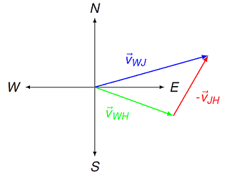
Fig. 9.6 Velocities of the JUNIPER and WILLOW, seen by an observer in Newport
Answer: 16.9 m/s, 15.6\(^\circ\) north of west
9.5. Summary
Relative motion is the description of how moving objects view each other. It plays a key role in the sea services, whether you are on a submarine, ship, or aircraft. We have seen here the defining vector equations used to study relative motion, and shown how these work in both one- and two-dimensional motion. This includes programming such motion into vPython, and viewing a scene from the standpoint of various moving objects. Relative motion also allows us to generalize the notion of collisions in the center of mass reference frame to any general situation, with an arbitrary value of the system’s momentum.
After this lesson you should be able to:
Find the velocity of one moving object as seen by another moving observer.
Use relative motion to find the final velocities in a generic 1D collision.